
Description
Product Overview
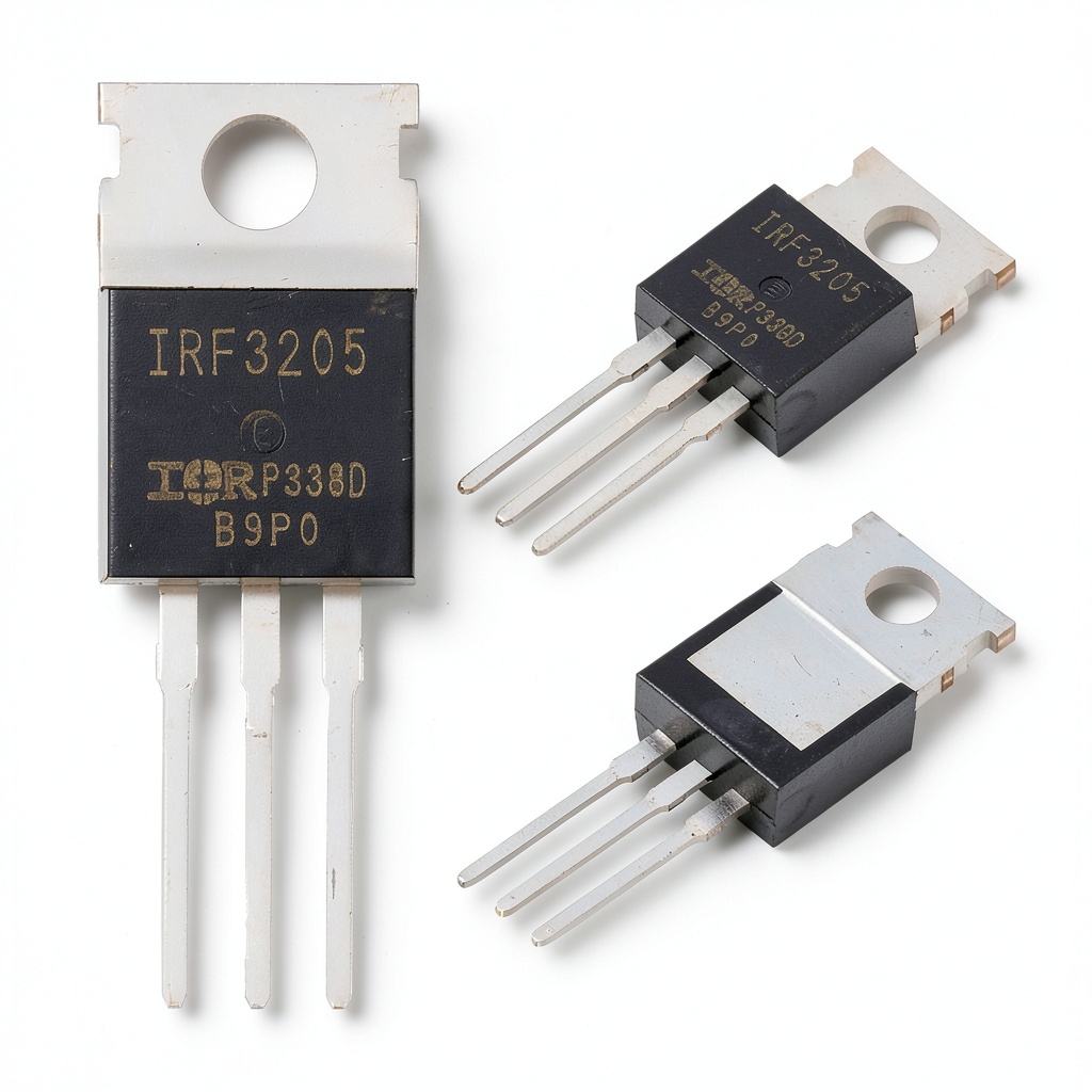
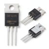
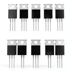
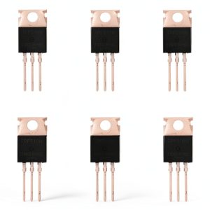
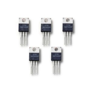
The IRF3205 MOSFET from YFUSET is a high-current, N-channel power transistor designed for demanding industrial and scientific applications. Housed in a robust TO-220 package, the device combines a 55V drain-source breakdown voltage with a continuous drain current rating of 110A and a pulsed current capability of 390A. Its exceptionally low on-resistance of 8mΩ reduces conduction losses, while the gate-to-source voltage tolerance of ±20V provides flexible drive options. These specifications make the IRF3205 suitable for high-speed switching, power conversion, and motor control circuits where efficiency and thermal performance are critical.
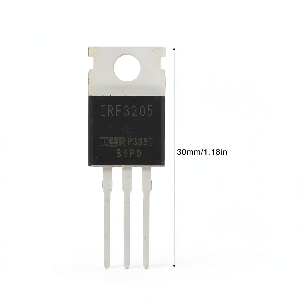
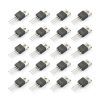
The datasheet lists a maximum junction temperature (T J) range from –55°C to 175°C, allowing operation in both low-temperature and high-temperature environments. The device’s gate threshold voltage lies between 2V and 4V, ensuring reliable turn-on characteristics while minimizing gate drive power. With a drain-source on-resistance (RDS(on)) of only 8mΩ at a gate voltage of 10V, the MOSFET delivers high efficiency even under heavy load conditions. The package dimensions of 0.2×0.2×0.2 inches and a weight of 1.6 oz provide a compact footprint for dense board layouts, and the lead-frame design facilitates effective heat sinking.
Because of its low RDS(on) value, the IRF3205 minimizes voltage drop across the device, which translates into lower heat generation and higher overall system efficiency. In power supply designs such as buck converters or boost converters, this reduction in loss can improve conversion efficiency by several percentage points, extending battery life in portable applications and reducing cooling requirements in stationary installations. The high current capability also enables the MOSFET to drive low-impedance loads, making it a preferred choice for motor driver circuits that demand rapid current changes and precise speed control.
The wide operating temperature range, combined with a robust silicon die and a reinforced TO-220 housing, ensures that the IRF3205 can withstand harsh industrial environments. The device is rated for a maximum power dissipation of 300W when properly mounted on a heatsink, allowing designers to implement compact thermal solutions without sacrificing performance. Additionally, the MOSFET’s built-in protection features, such as avalanche energy handling and safe operating area (SOA) compliance, provide resilience against voltage spikes and over-current events commonly encountered in switching power supplies.
YFUSET adheres to ISO-9001 quality management standards throughout the production of the IRF3205 MOSFET, employing automated wafer processing and rigorous testing at each stage. Each batch undergoes parametric verification, thermal cycling, and reliability screening to confirm compliance with the specified electrical characteristics. This systematic approach reduces variability and ensures that every transistor delivered meets the high performance expectations of engineers working on critical power electronics projects.
Thermal performance is a critical factor for high-current MOSFETs, and the IRF3205’s TO-220 package is engineered with a large copper tab that serves as an efficient heat sink. When mounted on a properly sized aluminum heatsink with a thermal interface material, the device can dissipate up to 300W while maintaining junction temperatures below the 175°C limit. The low thermal resistance of the package, typically around 0.5°C/W, ensures that heat is quickly transferred away from the silicon die, preserving the transistor’s electrical parameters and extending its operational lifespan even under continuous heavy-load conditions.
The IRF3205 exhibits fast switching characteristics, with typical turn-on and turn-off times in the low nanosecond range, enabling high-frequency operation up to several hundred kilohertz. Its gate charge of approximately 120nC and input capacitance of 2.5nF support rapid voltage transitions, which is essential for pulse-width modulation (PWM) control schemes used in modern power converters. The combination of low gate charge and low on-resistance reduces overall switching losses, allowing designers to achieve higher efficiency and lower electromagnetic interference (EMI) in compact, high-density power modules.
Reliability testing of the IRF3205 includes accelerated life tests such as high-temperature operating life (HTOL) and power cycling, which have demonstrated a mean time to failure (MTTF) exceeding 10,000 hours at 125°C. The device also undergoes electrostatic discharge (ESD) testing up to 2kV to ensure robustness during handling. These rigorous validation procedures confirm that the MOSFET can sustain long-term operation in demanding power electronics environments without performance degradation.
Usage
The IRF3205 is frequently selected for use in uninterruptible power supply (UPS) inverter stages, where its ability to handle high surge currents and maintain low conduction loss improves system reliability. Solar inverter designs benefit from the MOSFET’s high voltage rating and efficient switching, enabling greater energy harvest from photovoltaic panels. In motor drive applications, the device’s fast switching speed and low on-resistance support precise torque control and reduced acoustic noise. Additionally, the transistor is suitable for DC-DC converters, battery charger circuits, and high-frequency pulse width modulation (PWM) controllers across a range of industrial and renewable energy systems.
When integrating the IRF3205 into a PCB layout, designers should place the MOSFET close to the heat sink and minimize the length of the source and drain traces to reduce parasitic inductance. Using a copper pour on the drain side helps spread heat and lower the overall thermal resistance. Gate drive circuits should provide a voltage of at least 10V to achieve the specified RDS(on) while respecting the ±20V gate-source limit. Adding a small gate resistor (10–100Ω) can dampen ringing and improve switching stability in high-frequency applications.
The IRF3205 is compatible with a wide range of driver ICs, including popular gate drivers such as the IR2110, FAN7388, and TC4420, which can provide the necessary voltage levels and switching speed. Its standard TO-220 footprint aligns with common mounting patterns, allowing it to be used alongside other power devices on the same board without requiring special mechanical accommodations. The MOSFET’s electrical characteristics also make it suitable for parallel operation, enabling designers to share current load across multiple devices for even greater current handling capability.
Proper safety considerations include ensuring that the MOSFET’s drain-source voltage never exceeds its 55V rating and that the gate voltage remains within the ±20V limit to avoid dielectric breakdown. Designers should incorporate appropriate snubber circuits or clamping diodes to protect against inductive kickback in motor drive applications. Thermal monitoring, such as using a temperature sensor on the heatsink, helps prevent overheating and extends the component’s service life.
In industrial automation, the IRF3205 is well suited for motor drive circuits that require precise speed regulation and rapid current modulation. Its ability to handle high pulsed currents up to 390A enables it to support the transient demands of servo motors and variable-frequency drives (VFDs). The MOSFET’s low on-resistance reduces heat buildup during continuous operation, which is advantageous in confined enclosures where airflow may be limited. Engineers can integrate the device into PLC-controlled systems to achieve reliable, high-performance actuation across a range of manufacturing processes.
Renewable energy installations, such as solar photovoltaic inverters and wind turbine converters, benefit from the IRF3205’s high voltage tolerance and efficient switching. The MOSFET’s low conduction loss helps maximize the power extracted from solar panels, while its robust thermal design accommodates the fluctuating temperature conditions typical of outdoor environments. By incorporating the device into maximum power point tracking (MPPT) circuits, system designers can improve overall energy yield and reduce the size of cooling infrastructure, contributing to more compact and cost-effective renewable power solutions.
Why Choose Us
The wide operating temperature range, combined with a robust silicon die and a reinforced TO-220 housing, ensures that the IRF3205 can withstand harsh industrial environments. The device is rated for a maximum power dissipation of 300W when properly mounted on a heatsink, allowing designers to implement compact thermal solutions without sacrificing performance. Additionally, the MOSFET’s built-in protection features, such as avalanche energy handling and safe operating area (SOA) compliance, provide resilience against voltage spikes and over-current events commonly encountered in switching power supplies.
YFUSET adheres to ISO-9001 quality management standards throughout the production of the IRF3205 MOSFET, employing automated wafer processing and rigorous testing at each stage. Each batch undergoes parametric verification, thermal cycling, and reliability screening to confirm compliance with the specified electrical characteristics. This systematic approach reduces variability and ensures that every transistor delivered meets the high performance expectations of engineers working on critical power electronics projects.
The product is covered by a limited one-year warranty that guarantees replacement for any units that fail due to manufacturing defects under normal operating conditions. Warranty claims can be processed through the distributor or directly with YFUSET’s customer service department, providing confidence for long-term projects.
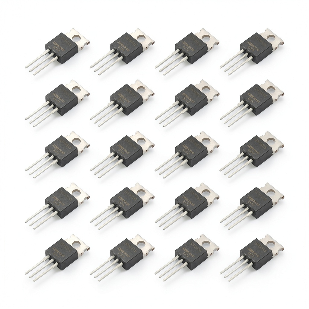
Customers can purchase the 20-piece kit of IRF3205 MOSFETs at a unit price of $9.99, which includes a bulk quantity that reduces per-device cost for large-scale builds. The package ships with the components securely packaged to prevent static discharge and includes a concise data sheet for quick reference during assembly.
In summary, the IRF3205 MOSFET from YFUSET delivers a combination of high voltage rating, large continuous current capacity, low on-resistance, and robust thermal performance, making it a versatile component for modern power electronics. Its compliance with industry standards and the availability of comprehensive technical resources simplify the design process for engineers across multiple sectors.
YFUSET maintains a reliable supply chain with multiple manufacturing facilities and strategic inventory locations, ensuring that customers receive consistent product availability and short lead times. This logistical advantage reduces project delays and allows engineers to plan production schedules with confidence, especially for large-scale deployments that require thousands of MOSFETs. The company’s commitment to continuous improvement also means that newer revisions of the IRF3205 incorporate incremental enhancements based on field feedback, further strengthening product performance over time.
Environmental stewardship is integral to YFUSET’s manufacturing philosophy. The IRF3205 is produced using lead-free soldering processes and adheres to RoHS and REACH regulations, minimizing the ecological impact of the component. Additionally, the device’s long operational life reduces the frequency of replacements, contributing to lower electronic waste. Customers seeking sustainable solutions can rely on the IRF3205 to meet both performance requirements and green-technology standards.
Key Features
- Low 8 mΩ on‑resistance reduces energy loss and heat
- Handles up to 110 A continuous current for high‑power designs
- TO‑220 package with large heatsink tab ensures effective thermal management
- Fast nanosecond switching enables efficient PWM and high‑frequency operation
- Backed by YFUSET technical support and a one‑year warranty for peace of mind
FAQ
What is the maximum safe operating temperature for the IRF3205?
The IRF3205 is rated for a junction temperature range from –55 °C to 175 °C. In practice, designers should keep the junction temperature well below the maximum, typically under 150 °C, to ensure long‑term reliability. This can be achieved by using an adequate heatsink, applying thermal paste, and monitoring temperature during operation. Exceeding the temperature limit can accelerate degradation of the silicon die and may lead to premature failure. It is also advisable to design for adequate airflow in the system enclosure to assist in heat removal.
How do I select an appropriate heatsink for the IRF3205?
Selecting a heatsink for the IRF3205 depends on the expected power dissipation and the allowable temperature rise. First, calculate the total power loss using P = I²·RDS(on) at the intended current. Then, divide the desired temperature increase by the thermal resistance of the heatsink (°C/W) to find the required heatsink rating. For example, at 100 A continuous current, the MOSFET dissipates roughly 80 W, so a heatsink with a thermal resistance of 1 °C/W or lower is recommended to keep the junction temperature within safe limits.
Can the IRF3205 be used in parallel to increase current capacity?
Parallel operation of IRF3205 devices is feasible and often employed to increase current handling capability. When connecting MOSFETs in parallel, it is important to match their gate and source resistances to ensure current sharing. Adding small source resistors (e.g., 10 mΩ) can help balance the currents and prevent one device from carrying a disproportionate load. Additionally, ensure that the combined thermal resistance remains within acceptable limits by providing adequate heatsinking for each device. Proper layout techniques, such as equal trace lengths and symmetrical placement, further improve current sharing and reduce parasitic inductance.
What gate drive voltage is recommended for optimal performance?
For optimal performance, the IRF3205 should be driven with a gate‑to‑source voltage of at least 10 V, which fully turns on the device and achieves the specified 8 mΩ on‑resistance. Gate voltages between 10 V and 12 V are common in most power applications. It is essential to stay within the ±20 V gate‑source limit to avoid damaging the gate oxide. Using a gate driver that can source and sink sufficient current ensures fast transition times and reduces switching losses. Typical gate resistors of 10–47 Ω help control the dV/dt and prevent ringing in high‑frequency circuits.
Is the IRF3205 suitable for automotive applications?
The IRF3205 can be used in automotive applications such as electric power steering, battery management, and DC‑DC converters, provided that the design meets automotive qualification standards. Its temperature range up to 175 °C and robust construction make it suitable for the harsh conditions found in vehicles. However, designers should verify compliance with AEC‑Q100 or ISO‑26262 requirements, and consider additional protection against voltage transients caused by inductive loads typical in automotive environments. Including transient voltage suppressor (TVS) diodes and proper grounding further enhances reliability in the automotive setting.
Reviews
There are no reviews yet.